Watt Hour Meter: Types And Structure

Watt-hour-meter structure:

⌲The construction of this relay is similar to the watt-hour-meter commonly used everywhere.

Structure of watt hour meter
Structure Of Watt hour meter

⌲It consists of E shaped electromagnet and a U shaped electromagnet with an aluminium disc free to rotate in between the upper electromagnet (E shaped) carries two windings, the primary and the secondary.

⌲Referring to show in fig: the primary winding carries relay current I, (also Known as C.T. secondary current) while secondary winding is connected to the winding of the lower magnet. 

⌲The primary current induces e.m.f. in the secondary winding and circulates current I2 in it.

⌲The flux o, induced in the lower magnet by the current in the secondary winding of the upper magnet will lag behind 0, by an angle @.

⌲The two fluxes 1 and 2 differing in phase by a will produce a driving torque on the disc proportional to 01 02 sin a.

⌲The operation of this type of relay can be controlled by opening or closing the secondary winding circuit. If this circuit is opened, no flux can be set by the lower magnet, consequently no torque will be produced. Therefore, the relay can be made inoperative by opening its secondary winding circuit.

Fluorescent Lamps: Principle, Construction & Operation

Fluorescent Lamps: Principle, Construction & Operation

Principle Of Fluorescent Lamp

"When fluorescent materials are subjected to electromagnetic rediations of particular wavelength, they get excited and in turn gives out rediations at some other length, and persist in giving out rediations even if exciting rediations are removed". 

Basic operation Fluorescent Lamp

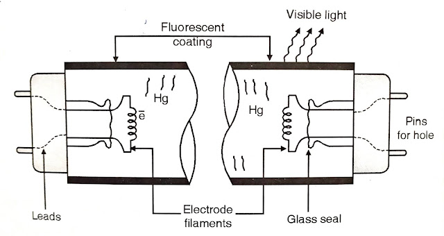
Fluorescent lamps, in principle is low pressure mercury discharge lap with internal surface coated with suitable fluorescent material.

Fluorescent tube construction
construction of fluorescent tube

Tube contains argon or krypton gas to case starting with small quantity of mercury under low pressure. At start, current is passed through filaments which get heated up and emit electrons which strike 'Hg' to give out rediations which fall on fluorescent material thus emitting light

Tube contains argon gas in small amount in vapour form and mercury in globular form i.e. not in pure vapour form. Argon gas is to initiate the arc.


Circuit diagram for fluorescent lamps with :

  • (a) Glow type starter :
  • (b) Thermal Type Starter: 

(a)Glow Type Starter:

✦In circuit diagram R and C are for protection purpose:

Tube with Glow Type Starter
Tube With Glow Type Starter Circuit Diagram

R-is to avoid welding of starter contacts and C-is to reduce radio interference.

✦Starter is made as two electrode E, and E, out of which E, is fixed and E₂ is of bimetallic strip. They are fitted into a glass tube having Helium and Hydrogen at low pressure.

✦Normally, the contacts E, and E, are open and when supply is applied full voltage is received by glow switch, this voltage is sufficient to start glow discharge between bimetallic strips E, and E, and heat generated bends E, to make contact with E, thus completing main circuit through choke and lamp electrodes A and B. 

Glow Type Starter
Glow Type Starter Working

✦Current starts flowing through A and B and are heated in incandescence and argon gas which is in immediate vicinity is ionized by this time glow is shorted out and so E, and E, cools and contacts open again.

✦Sudden rate of change of current induced a voltage surge about 1000 V across choke and initiates a discharge of argon gas and heat is produced. This heat is sufficient to vaporize mercury and potential difference falls to 100 to 110 V.

(b) Thermal type starter :

✦Two bimetallic strips initially closed so that current flows through filaments, heater coil, thus the electrodes A and R are heated to incandescence and argon gas is ionized.

✦Meanwhile, one of the bimetallic strip near to heater coil gets heated and bends thus interrupting filament current producing inductive voltage surge across electron -establishing discharge through mercury vapour. Starting time is very much less than the flow type starter.

Electroplating

Electroplating 

The deposition of superior or noble metal on an inferior or a lease metal by means of electrolysis of an aqueous solution of suitable electrolyte is called electroplating.

Electroplating is essential on metals like iron which can easily corrected by atmospheric it, moisture and carbon dioxide are coated by deposits of nickel or chromium. Electroplating is also used on metals to protect them from chemical attack and the same time to give them a good polish. 

Sometimes it is just alone for ornamentation and decoration purpose. Example may articles which are made of copper such as table vase, decoration pieces are coated with her or gold.

The electrolytic processes are crystalline in nature. The deposition must be very fine in under to get firm and uniform deposits. To achieve this suitable electrolytes and current density sed should have an appropriate value. The temperature should also be maintained at a proper level

Before electroplating the object some operations are to be done on the object. The persons are as follows:

1.Removal of the oil, grease or any other organic material. This can be done by using soaps, hot alkali solutions or organic solvents such as gasoline, or carbon tetrachloride.

2. Removal of rust, scale, oxides, or other inorganic coatings adhering to the material. They can be removed with the help of various acids, alkalies and salt solutions.

3.Mechanical preparation of the surface of the metal to receive the deposited metal by polishing buffing etc. For this electrolytic cleaning, mechanical abrasion and polishing are used.

The object to be electroplated is cleaned using different cleaning methods. If the object to be electroplated is not cleaned, polished and degreased the deposit formed may well adherent to the base metal and may peel off in due course of time. 

For smooth, bright and hard deposit, the surface of the object to be electroplated should be thoroughly cleaned first mechanically by grinding or scratching against the rough surface or sand blasting and then chemically by treating them with hot alkalies if the surface is greasy or with dilute acids if the surface has oxide films.

The electrolyte used in the electrolytic bath depends on the nature of the metal to be

deposited.

For copper plating:

For copper plating two types of electrolytic baths are used, the acidic bath and the

cyanide bath.

In acidic bath solution is made up of 150-200 gm of copper sulphate and 25-35 gm of sulphuric acid per 1000 cc of solution. Current density used is 150-400 A/m temperature is 25 to 50°C and the deposit obtained is thick, rough and requires polishing.

In cyanide bath solution is made of 28 gm of copper cyanide, 6 gm of sodium carbonate

and 6 gm of sodium bisulphate per 1000 cc of solution. Current density is 50-150 A/m² and

temperature is 25-40°C. It gives thin and smooth deposit. Copper electrodes are used in both baths.

For silver plating

silver- platting
silver- platting
 For silver plating the solution consists of 24 gm of silver cyanide, 24 gm of potassium carbonate and 36 gm of potassium cyanide per 1000 cc is used. The required current density is 50-150 A/m and temperature used is 20-35°C. For gold plating:

For Gold plating

Gold plating
Gold plating
                      

For gold plating the solution consists of 18 gm of potassium gold cyanide, 12 gm of potassium cyanide, 6 gm of potassium sulphate and 12 gm of caustic potash per 1000 cc. The electrodes are of stainless steel. The current density required is 50-150 A/m and temperature used is of 50°-70°C.

For chromium plating :

For chromium plating the most commonly used solution is of 180-300 gm of chromic acid and 2-3 gm of sulphuric acid per 1h000 ce of solution. The current density required is 1500-2500 A/m and the temperature is of 35-50°C. Anode are made of antimonial lead vats used for chromium plating are of steel with lead lining. Chromic acid is added to the solution at regular intervals.

For nickel plating:

For nickel plating the solution consists of 180-240 gm of nickel sulphate, 36 gm of nickel chloride and 24 gm of boric acid per 1000 cc. The current density used is 100-200 A/m² and working temperature is of 25-40°C. Anode is made of pure nickel.

Classification of Measuring Instruments.

Classification of Measuring Instruments.

Classification of Measuring Instruments. 

Electrical measuring instruments may be classified as direct measur ing instruments (such as ammeters, voltmeters, watt meters) and comparison instruments.

Direct measuring instruments convert the energy of the unknown quantity directly into the energy that deflects the moving elements of the instrument, the value of unknown quantity being measured by reading the resulting deflection.

Direct measuring instruments are most widely used in engineering practice since they are the most simple and index pensive ones and enable the measurements to be made in the shortest possible time. Comparison instruments are used in cases when a higher accuracy of measurement is needed.

Electrical measuring instruments may also be classified according to the kind of the quantity being measured (such as ammeters, voltmeters, watt meters, energy meters, ampere-hour meters, frequency meters, ohm meters, phase meters, or power factor meters), kind of current for which they are designed (such as de or ac), the principle of operation of the moving system such as magnetic, thermal, chemical, electrostatic and electro magnetic induction instruments), their accuracy class, protection against the influence of external fields, service conditions, ability against mechanical effects, fields of application, method of installation and mounting or shape and size of the instrument ases and the degree of enclosure they provide.

According of BIS 1248 (1968), accuracy classes are 0.05, 1, 0.2, 0.5, 1, 1.5, 2.5 and 5. These figures are indication of erce tage error-instrument of accuracy class 0.2 means that the stringent can have an error up to +0.2% of full-scale deflection. 

The electrical measuring instruments may, in very broad Ense, be divided into two classes namely absolute and second y instruments. Absolute instruments give the quantity under easureme to in terms of instrument constant and its deflection d do not need any comparison with any other standard instrument. 

Secondary instrument gives deflection in proportion to the magnitude of electrical quantity under measurement di- recruitment. Absolute instruments are mostly used in standard labora tories and similar institutions as standardized instruments and secondary instruments are widely used in practice.S

Secondary instruments are further classified into three groups namely indicating instruments (such as ordinary ammeters, voltmeters, watt meters, frequency meters, power factor meters etc.), recording instruments (such as graphic recorders, galvanometer recorders, null balance recorders, etc.) and integrating instruments (such as ampere-hour meters and energy meters).

Construction and Working of sodium Vapour Discharge Lamp

Sodium Vapour Discharge Lamp

1. Principle Sodium Vapour Discharge Lamp

Electrons are emitted from cathode  subjecting the surface of the cathode to very  good high electric stress so thay electrons are forcibly ejected from orbits of atom against nuclear centripetal force".

2. Construction and Working Of Sodium Vapour Discharge Lamp

It consists of inner tube of U shape fitted with neon gas and globules of sodium.  For good performance 300°C temperature is to maintained.

To protect discharge tube it is contained in evacuated double walled glass jacket this  prevents heat loss.

Sodium Vapour Lamp
Sodium Vapour Lamp
•At starting, electric discharge is to be established through neon gas till sodium gas vapourized, so at start for 10-15 min. discharge through lamp will be pink and then as sodium vapourizes, it will turn to yellow.

• For this voltage of about 410 is required white normal voltage is about 165. Supply is given through a leak transformer which has high leak reactance.

• As soon as discharge through the tube starts, heavy voltage drop takes place in the transformer so that required operating voltage is automatically impressed across cathodes. 

• P.F. there are  lamps is 0.3 lagging and there condenser can be used for P.F. connected.

3. Precaution of Sodium Vapour Discharge Lamp

Care should be taken in handling these lamps, for if inner tube is broken and sodium comes in contact with moisture, fire will result.


4. Life Sodium Vapour Discharge Lamp

Normal average life of sodium vapour lamps is 2500 hrs. 

5. Applications of Sodium Vapour Discharge Lamp

due to yellow light use for fox light, street light, party light socks quarries etc docket,quarries etc


6. Sizes available of Sodium Vapour Discharge Lamp

45, 60, 85, 140 W.

Metal Halide Lamp

Metal Halide Lamp

There are lamp is known as  metal halide lamp. It has a short Are tube.

Series led lamp  output characteristics of different mixtures of elements. When such metals (like thallium, indium, sodium, dysprosium) are introduced into mercury are tube, the mercury spectrum is suppressed reducing the ultraviolet radiation but added metal atoms partly compensate sell by  causing a wide range of spectral bonds to be emitted. 

Metal Halide Lamp
It is possible product  to all color available If the the discharge tube.  its halide is used like iodide i.e. sodium iodide. The lamps require high starting voltage. 

This is provided by ignitor as shown connector show in the Fig. Ignitor is connected across the lamp terminals. 

This type of starter (ignitor) enables the lamp tu be restruck within  a minute of being switched off.

Control Circuit With Ignitor For an Metal Halide Lamp


Use: 

Used for high bay interior and high mast exterior installations.

Sport stadium where coloured T.V. transmission is expected. 

Flood lighting projectors.


ELECTRICAL ENGINEERRING MATERIALS CLASSIFICATION

ELECTRICAL ENGINEERRING MATERIALS CLASSIFICATION

CLASSIFICATION OF MATERIALS 

Electrical Engineering materials may be divided into four broad groups according to the purposes they serve. 

These four groups are: 

  1. conductors, 
  2. semiconductors, 
  3. magnetic materials, and 
  4. electrical insulating materials or dielectrics. 

Conductors possess high conductivity and are used in Electrical Engineering to provide paths for electric current in all types of electrical machine windings, electrical apparatus, devices, instruments, etc. 

Conductors are required for the manufacture of cables and wires by means of which electrical energy is transmitted over long distances and then distributed to the consumers.

Semiconductors occupy an intermediate position between conductors and insulators (or dielectrics). The properties of semiconductors make them valuable in many branches of Electrical Engineering such as telecommunication and radio communication, electronics in general (over a wide range of frequencies) and power engineering. Semiconductors serve as rectifiers, amplifiers, special sources of electric current, photocells, etc.

Magnetic materials strengthen the magnetic field in which they are placed and possess high magnetic permeability. These properties make them suitable for use as magnetic cores and circuits, magnetic screens, and permanent magnets enabling setting up a magnetic field in the surrounding space.

The characteristic property of electrical insulating materials is poor conductivity. The great quantitative difference between the conductivity of dielectrics and conductors leads to a distinctive qualitative difference between them.

The behaviour of the dielectrics is not governed by electrodynamic phenomena involving the directional flow of enormous number of electric charges (free electrons or ions) but by electrostatic phenomena associated with the presence of an electric field. 

The behaviour of real dielectrics is primarily electrostatic; electrodynamic effects, that also take place due to their non-zero conductivity, are quite insignificant in normal operating conditions. 

In all kinds of electrical devices and circuits dielectrics serve to insulate one current carrying part from another whenever they operate with a difference in electrical potential relative to each other. 

In capacitors dielectrics also serve to provide some required value of capacitance. The dielectrics used in electrical engineering may be gases, liquids or solids. 

Among the gases that serve as dielectrics are air, nitrogen, and others. Liquid dielectrics may be natural (for example mineral insulating oils) artificial. Solid dielectrics are extremely diverse in origin and properties.