Essential Qualities Of Protection

Essential Qualities Of Protection

 As soon as the fault occurs on the power system, protection scheme should disconnect/isolate the faulty part as quickly as possible to minimize the damage to the system and to maintain the continuity of supply. Protective scheme may have following qualities :

1.Sensitivity: 

Ability of the protective system to operate with low values of actuating quantity is known as sensitivity. The protective system should be enough sensitive to operate with the small quantity of fault current.

2.Speed: 

As mentioned above, the protective system should disconnect the faulty part as quickly as possible for the following reasons:

  • If the fault current is allowed to flow for the longer time  then there will be considerable damage to the equipments which are feeding the fault. 
  • If the fault is not cleared quickly, then it is possibility of development of temporary fault in to permanent fault.

  • If the faulty parts of the system are not cleared quickly then it is the possibility of spreading these faults into healthy parts of the system. 
  • A fault on the system causes the reduction in the terminal voltage, causing the complete shut down of consumer's motors. Also the generators on the system may become unstable.

3.Selectivity: 

The ability of the protective system to select correctly the faulty part of the system and disconnect that part without disturbing the rest of the system is known as selectivity.

  • Protective system should operate the circuit breaker which is nearer to the fault otherwise, opening of any circuit breaker to clear the fault will lead to disconnect the greater portion of the power system. Refering to Fig.  if the fault occurs on the transmission line (which is located by point F), then operating of circuit breakers 6 and 8will cause minimum disconnection of the power system portion. 
  • In order to provide, selectivity to the system, the entire system is divided into several protective zones. When a fault occurs in a given zone, then only the circuit breakers within that zone be opened. This will isolate only the faulty section and the remaining healthy is unaffected.

Different Protective Zone

4.Reliability: 

The ability of the protection system to operate under the predetermined conditions is known as reliability. The protection would be rendered largely ineffectively and could even become a liability without the reliability.

5.Simplicity: 

A simple protective system is easy to maintain Reliability and Simplicity are closely related. The simpler the protection scheme, the greater will be its reliability.

6.Adequate ness:

 Providing protection scheme for every abnormal condition is very costly. Therefore, protection provided for any machine should be adequate.

Adequate ness of protection is judge by following aspects : 

  • Cost of the machine and importance of the machine.
  • Rating of the machine to be protected.
  • Probability of abnormal conditions due to internal and external causes.
  • Continuity of supply as affected by failure of machine.
  •  Location of protected machine.

7.Economy:

Cost is the most important factor in the choice of a particular protection scheme. As a rule, the protective gear should not cost more than 5% of its total cost. However, when the apparatus to be protected is of at most importance, then economic considerations are often subordinated to reliability.

Reverse Power Protection

Reverse Power Protection :

•When the input to the turbine is failed, the generator continues to rotate as a synchronous motor and draws power from the bus bars. 

•Turbine acts as a load on synchronous motor and continues drawing the electrical power.

•During the motoring action of the generator, the power flows from the bus bars to the machine and the conditions in the three phases are balanced. 

•Normally the power taken by synchronous motor is low of the order of 2 to 10% of the rated power. Power factor and current depends on excitation level.

Direction Power Relay
Circuit Diagram Of Direction Power Relay
              

•Hence single element directional power relay (reverse power relay) is used to sense the direction of power flow.

•The CTs for reverse power protection may be either at the neutral end or the bus bar end of the generator winding.

Operating Characteristics Of Reverse Power Operation


•Intentional time lag is provided in the reverse power protection so that the protection does not operate during system disturbances and power swings.

Overhead Ground Wires

Overhead Ground Wires :

☛Overhead transmission lines have the thousands of kilometer age run also they are exposed to atmosphere hence, the chances of lightening stroke on overhead lines are more than any other equipments of power system.

☛The ground wire provides the perfect protection against the lightening stroke

for overhead lines.

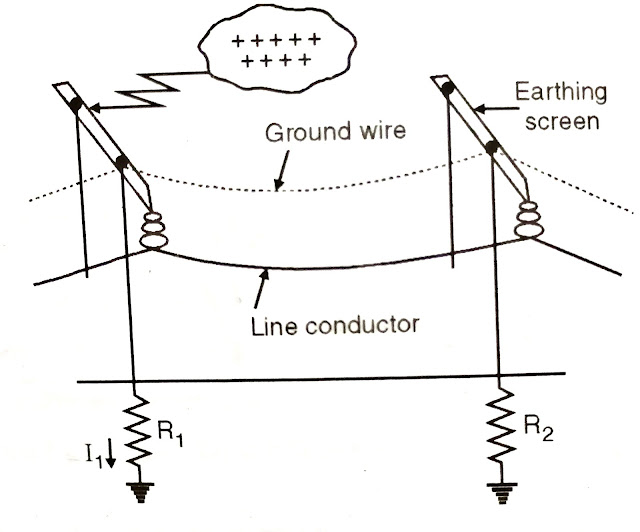
☛The ground wire is placed above the line conductor i.e at the top of the tower.

☛The arrangement is as shown in Fig.

☛When the direct lightening stroke occurs on the transmission line, it is subjected on the ground wire instead of transmission line since the ground wire is the tallest object in this case. 

☛Since the ground wire is earthed at each pole/ tower through low impedance, the heavy lightening current from the ground wire flows to the ground, thus protect the overhead transmission line from the harmful effects of lightening.

☛It may be mentioned here that the tower footing resistance of the tower decides the degree of protection provided by the ground wires.

☛Suppose V, is the approximate voltage between tower and line conductor 

☛And V, is also the voltage that will appear the string of insulator, which is given by I₁R₁

Where   I₁= Lightening current flowing through the tower to ground.

               R₁= tower footing resistance.

☛If the value of V, is less than insulator flashover voltage then no trouble occurs.

☛Since the value of V, depends upon the tower footing resistance R, the value of this resistance must be kept as low as possible to avoid insulator flashover.

Ground Wire Connection

      Overhead Ground Wires


Advantages of Ground Wire

(1) Ground wire provides considerable protection against direct lightening strokes on transmission line.

(2) It provides a certain amount of electrostatic shielding against external

fields. Thus it reduces the voltage induced in the line conductor due to the discharge of a neighboring cloud.

(3) Since the grounding wire acts as a short-circuited secondary it provides damping effect on any disturbance travelling along the line.

Disadvantages of Ground Wire

(1) Since the ground wire has to run along the length of transmission line, it requires additional cost. 

(2) There is a possibility of breaking and falling of ground wire across the line conductors, further it causes a short-circuit Fault.

☛Using galvanised stranded steel conductors as ground wires can eliminate this difficulty. Galvanized stranded steel provides sufficient strength to the ground wires.

Transfer Trip or Inter Trip

 Transfer Trip or Inter Trip

❀The faults at both the ends (20 % on each side) of the transmission line which sums up to be 40 % of the line length fall in the second step of the distance protection.

❀This therefore receives a delayed protection service.

❀Thus only about 60% of the need length of the transmission line gets a high speed distance protection.

❀In case fault which is in the end 40 % section the nearest distance protection trips simultaneously but the remote end protection is delayed and there is a problem of speeding up the remote end distance protection.

❀As shown in the Fig.  Z1, Za and Za are considered for the carrier signal communication during a fault condition.

❀If we consider a fault in the second zone of distance protection but not beyond end B as seen from the end A, then one can make use of first zone Z contact of the local relay at the end B to initiate a carrier and remotely operate a contact to close the trip circuit of the remote circuit breaker at the end A.

Acceleration of zone
Acceleration of zone Diagram


➡️The logic of the protection scheme works on the following lines:

1. The Zi contact of the local relay at the end B operates and changes from its No  position to CLOSED position.

2. This closure action of the contact is used to switch ON the carrier transmitter T. at the end B.

3. This carrier transmitter injects a carrier signal in to the line.

4. This carrier signal arrives at the remote end A at the speed of light after a very short delay and received by a carrier current receiver, R.

5. This carrier current receiver gives an output at the Carrier Receipt Relay, CRRA at the end A.

❀The contact of CRRA can be used to energies the trip coil of the circuit breaker at the remote end A in various alternative ways.

❀If the fault detector Fo contact is bypassed by connecting point P with P then the scheme is known as transfer trip or inter trip.

❀In case of transfer trip or inter trip the carrier signal is needed for tripping purposes and during the failure of carrier equipment or during the severe attenuation of the carrier signal due to fault the entire operation of the scheme is put at danger.

❀Therefore the tripping carrier scheme does not provide robustness. The carrier based scheme is expected ideally to be such that in case of failure of carrier it should automatically revert back to the three stepped distance scheme.

❀This type of logic can be built up in such a way that the carrier signal is not required for tripping but it is required for blocking the tripping.

❀If such schemes are used they obviously offer more robustness and such schemes are known as blocking carrier schemes.

Restricted Earth Fault Protection :

 Restricted Earth Fault Protection :

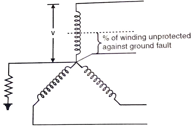
➤Usually it is a practice to connect the neutral of star connected generator to the ground. (Various advantages of providing neutral grounding are explained in previous article) When neutral is solidly grounded, it is possible to protect complete generator or transformer winding against phase to ground fault.

➤But usually neutral of generator or transformer winding is earthed through resistance/inductance to limit earth fault currents. 

➤winding from earth fault and the % of winding protected depends on the value of neutral earthing resistor and the relay setting.

➤Generally 80 to 85% of generator winding is protected against earth faults using differential protection. The remaining 20 to 15% winding from neutral side left up protected by the differential protection.

➤To achieve 100% protection against earth faults, a separate earth fault protection is provided in addition to differential protection.

➤On the occurrence of earth fault, fault current Ir flows thoght  a part of the dc ganartor winding and neutral to ground  circuit.

➤The corresponding secondary current of current transformer I. flows through the operating coil and restricted earth fault coil of the differential protection.

➤ If the earth fault occur at point f of the generator winding, voltage Vat is available to drive earth fault current Ir through the neutral to ground connection

➤If fault occurs near to neutral point i.e. terminal 'a', the driving voltage Var will be very less. Hence earth fault current It is having considerably low value.

Percentage Differential Protection
Percentage Differential Protection with Restricted Earth Fault Relay


➤Relay setting can not be kept to a very low value (i.e. setting the relay too sensitive to sense the earth fault currents of small magnitudes). Because if too sensitive the relay may respond during through faults or other faults due to inaccuracies of CTs or saturation of CTs etc.

% Of Winding Unprotected Against Ground Fault


➤As separate earth fault protection covers the entire winding against earth faults.

Over Current and Earth Fault Protection for Generator Backup

Over Current and Earth Fault Protection for Generator Backup :

➡️It is true that the protection scheme provided for the generator should not operate for through fault (faults beyond protective zone) conditions. But generator is the source by which any fault on the system is going to feed by it only, protection against such abnormal conditions should be provided.

➡️For generators above 1 MW where primary protection to stator winding is provided by differential protection and the over current and earth fault protection gives back up protection for external phase to phase faults and earth fault.

➡️Since the faults in stator winding are fed by the stator winding itself, their influence on current in the outgoing terminals of generator depends upon fault level of the main bus.

➡️Hence over current and earth fault relays do not provide satisfactory protection against internal faults.

➡️However the over current and earth fault relays provide back up protection to generator against external faults (faults in bus zone, transmission zone) The setting of over current and earth fault protection is selected such that relay does not operates for through faults.

Sequence of operation

➡️However if fault F continues for a long time due to failure of line protection (1) the fault will be fed by the generator. Hence the over current and earth fault protection of generator (3) may be set to operate with due time lag for higher values of external fault currents.


➡️Hence high set, definite minimum time, induction type inverse over current, earth fault relays are recommended for generator back up.

Over Current Protection
Back up protection by over current protection

Fig:-(b) Back up protection by over current protection

Sensitive Earth Fault Protection

Sensitive Earth Fault Protection :

• As explained in section 4.4, differential protection does not protect the 100 % portion of generator stator winding against earth faults. Hence a separate sensitive earth faults protection is necessary.

• Two methods are available to provide protection for remaining 15 % of stator winding from neutral connection.

• For large units, Generator neutral is earthed through high impedance, to limit the maximum earth-fault current to much lower value than full load current, Fig.  (a). This method is preferred for large units.

• With resistance earthing Fig.  (a) two earth fault relays may be provided on the secondary side of neutral CT. The first E. F. (earth fault) relay is set at 10 percent and is instantaneous type. 

• The second E. F. relay is inverse definite minimum time (IDMT) and is set at 5 percent (the relay pick up when earth fault current is 5 percent of full load current of generator).

• Depending upon the sensitivity, the first relay would protect about 90 percent of stator winding and the second relay about 95 percent. For such sensitive settings, it is necessary to provide a time delay, otherwise the relay may respond to transient neutral currents during external faults. 

Sensitive Earth Fault Protection
Sensitive Earth Fault Protection 

 • Refer Fig.(b), when neutral is connected through VT; the rated primary voltage of VT is generally equal to neutral to earth voltage of generator.

• The E. F. relay is connected to secondary of VT with setting of 10% of rated secondary voltage of VT.

Sensitive Earth Fault Protection


• When the voltage between neutral and earth reaches 10 % of phase to neutral voltage of generator, the earth fault relay operates.

• Lighting Arrester connected in parallel with the primary protects the VT from high voltage surges.