Type of construction of CT's:

Type of construction of CT's: 

Ring type CT or Window type CT:

This is the simplest type of CT. The core has three types of popular shapes (1) Rectangular shape (2) Oval shape (3) Ring shape.

Ring Type CT
Ring Type CT

Bar primary current transformers:

✥The core is of a Nickel-Iron Alloy, or grain oriented sheet steel. 
✥The core is continuously wound type. Before applying secondary winding,
the core is insulated by means of end collars and circumferential wraps.

Bar Primary Current Transformer


✥Recently the continuously wound cores are available in encapsulated form. Synthetic resins are used as encapsulating material.
✥The material is applied by fluidized beds or electrostatic spraying.

(A)Core of A Ring Type CT
(B) Core is taped with insulting tape

(C)Secondary winding wound on core by toroidal winding machine

(D)Exterior taping is completed with circumferential insulating wraps

✥The secondary winding conductor is then wound as the insulated core in the form of toroidal winding by hand winding or toroidal winding machine. 
✥The secondary winding is then completely wrapped by external tape with or without exterior ring ends and circumferential insulating wraps.

Current transformers for high voltage installation : 

✥Separately mounted post type CT's They are suitable for out door service.
✥They are usually installed in the outdoor switchyard.
✥The primary conductor is at voltage with respect to earth. Hence it insulated by means of an insulator column filled with dielectric oil. Alternatively SF6 gas at a pressure of 2 or 3 atmospheres is now being used.

CT for high Voltage
CT for high Voltage


Essential Qualities Of Protection

Essential Qualities Of Protection

 As soon as the fault occurs on the power system, protection scheme should disconnect/isolate the faulty part as quickly as possible to minimize the damage to the system and to maintain the continuity of supply. Protective scheme may have following qualities :

1.Sensitivity: 

Ability of the protective system to operate with low values of actuating quantity is known as sensitivity. The protective system should be enough sensitive to operate with the small quantity of fault current.

2.Speed: 

As mentioned above, the protective system should disconnect the faulty part as quickly as possible for the following reasons:

  • If the fault current is allowed to flow for the longer time  then there will be considerable damage to the equipments which are feeding the fault. 
  • If the fault is not cleared quickly, then it is possibility of development of temporary fault in to permanent fault.

  • If the faulty parts of the system are not cleared quickly then it is the possibility of spreading these faults into healthy parts of the system. 
  • A fault on the system causes the reduction in the terminal voltage, causing the complete shut down of consumer's motors. Also the generators on the system may become unstable.

3.Selectivity: 

The ability of the protective system to select correctly the faulty part of the system and disconnect that part without disturbing the rest of the system is known as selectivity.

  • Protective system should operate the circuit breaker which is nearer to the fault otherwise, opening of any circuit breaker to clear the fault will lead to disconnect the greater portion of the power system. Refering to Fig.  if the fault occurs on the transmission line (which is located by point F), then operating of circuit breakers 6 and 8will cause minimum disconnection of the power system portion. 
  • In order to provide, selectivity to the system, the entire system is divided into several protective zones. When a fault occurs in a given zone, then only the circuit breakers within that zone be opened. This will isolate only the faulty section and the remaining healthy is unaffected.

Different Protective Zone

4.Reliability: 

The ability of the protection system to operate under the predetermined conditions is known as reliability. The protection would be rendered largely ineffectively and could even become a liability without the reliability.

5.Simplicity: 

A simple protective system is easy to maintain Reliability and Simplicity are closely related. The simpler the protection scheme, the greater will be its reliability.

6.Adequate ness:

 Providing protection scheme for every abnormal condition is very costly. Therefore, protection provided for any machine should be adequate.

Adequate ness of protection is judge by following aspects : 

  • Cost of the machine and importance of the machine.
  • Rating of the machine to be protected.
  • Probability of abnormal conditions due to internal and external causes.
  • Continuity of supply as affected by failure of machine.
  •  Location of protected machine.

7.Economy:

Cost is the most important factor in the choice of a particular protection scheme. As a rule, the protective gear should not cost more than 5% of its total cost. However, when the apparatus to be protected is of at most importance, then economic considerations are often subordinated to reliability.

Type of Lightening Strokes

Type of Lightening Strokes

There are two main ways in which a lighting may strike the power system:

(a)Direct stroke.
(b) Indirect stroke.

(a)Direct stroke:

☛In case of direct lightening stroke, the charge from the cloud is directly discharged on the object below it.

☛After discharging, the current finds the path through the insulator to the pole to the ground.

☛The over voltage set up due to the lightening stroke has a very large magnitude and may cause flashover or puncture of line insulator.

The direct strokes can be classified as:

1) Stroke A

2) Stroke B

Direct lightening stroke

(i) Fig. shows the direct lightening stroke. It can be explained in two ways. Referring to first figure, suppose a overhead transmission line is exactly below the positively charged cloud and there is no more cloud near to this one, then the lightening discharge will occur from the cloud to the object (i.e. overhead line) below it. In this case the cloud will induce a charge of opposite sign on the tall object.

When the potential between the cloud and line exceed the breakdown value of air, the lightening discharge occurs between the cloud and the line. 

(ii) Referring to second figure if there are three clouds P, Q and R having positive, negative and positive charge respectively then the charge on the cloud Q is bound by the charge on cloud R.

☛If the cloud P shifts too near the cloud Q, then lightening discharged will occur between them and a charge on both these clouds disappears quickly.

☛The result is that charge on cloud R suddenly becomes free and it then discharges rapidly to earth, ignoring tall objects.

☛i.e.in second case the lightening discharge occurs on the overhead line as a

result of stroke A between the cloud P and

(b) Indirect stroke:

☛The charged cloud always creates the equal and opposite charges on the object below it by the electrostatic action.

☛Assume that a positively charged cloud is exactly above the overhead line.

☛Thus it creates the negative charge of equal magnitude on it. 

If the cloud discharges to earth or
other neighbouring cloud, the negative charge on the line is left behind.
☛The result is that negative charge rushes along the line is both directions in the form of travelling waves.
Indirect Lightening stroke
☛It may be worthwhile to mention here that majority of the surges in a transmission line are caused by he indirect lightening strokes.

Lightening Arresters

Lightening Arresters:

• Protection against direct lightening strokes is provided by using the earthing screen and ground wires. But these two apparatus fail to provide protection against travelling waves; which may reach the terminal apparatus.

• The lightening arresters or surge diverters provide protection against such surges.

(A) Construction of Simple L.A

• A lightening arrester or a surge diverter is a protective device, which diverts the high

voltage surges on the power system to the ground.

Characteristics of non- linear resistance
(B) Characteristics of non- linear resistance

• Fig. 4.39.2 (a) shows the basic construction of a lightening arrester. It mainly consists of a spark gap and a non-linear resistor in series with it. 

• One end of the surge diverter is connected to the terminal of the equipment to be protected and the other end is effectively grounded.

• The air gap between the spheres is so adjusted such that under normal line

voltage this gap does not produce any are. But a dangerously high voltage will breake

down the air insulation and form an arc.

• The non-linear resistance is the resistance which having the non-linear characteristics i.e. the magnitude of resistance decreases as the voltage (or current) increases and vice-versa. Fig. 4.39.2 (b) shows the volt /Amp characteristic of the non-linear resistor.

Working:

The action of the spark gap lightening arrester or surge diverter is explained

follows:

(i) Since the spark gap and non-linear resistance provides very high resistance to normal operating voltage, the lightening arrester conducts no current to earth or the gap is non- conducting. 

(ii) When the over voltage occurs on the system, the air insulation across the gap

breaks down and an arc is formed.

(iii) Now the non-linear resistance provides a low resistance path for the surge to the ground. In this way, the excess charge is diverted towards the earth and hence equipment is protected against failure.

(ii) It should be noted that while designing a lightening arrester that when the surge is over the are in gap should cease. Otherwise if the arc does not go out, the current would continue to flow through the resistor and both resistor and gap may be destroyed.

Types of Resistance Welding

Types of Resistance Welding:(A)Butt welding:

❉ Rods, pipes and wires are welded by this method. As shown in Fig. (A) there is a transformer, across secondary of the transformer two pieces of metal to be welded are held. The two pieces are held in clamps. One clamp is fixed and other is movable

(A)Butt welding

          (A) Butt welding

❉ The pieces of pipe are made to touch each other and force/pressure is applied through springs. When supply is given to transformer, current passes through the pieces of pipes and sufficient heat is developed at the joint causing welding at the joint.

(B)Flash butt welding:

❉ This is modification of butt welding. The ends of the pipe to be welded are held together with a little force/pressure applied to them. Arcing at the joint is allowed to take place. This removes any unevenness at the joint. A weld having a fin around the joint is obtained Fig.(B)

(B)Flash butt welding

       (B) Flash butt welding

❉ The fin can be easily removed. Two dissimilar metals can be effectively welded with this method. This welding method is faster than other methods.

(C)Spot welding:

❉ In spot welding, the welding is done at certain points on metallic sheets. The pieces to be welded are held between the two electrodes as shown in Fig.(C)

(C)Spot welding

            (C) Spot welding

❉ When current passes through the electrodes a spot weld is produced between the sheets.

(D)Projection welding :

❉ It is a modified form of spot welding. The electrodes used are flat and not pointed as in case of spot welding.

(D)Projection welding :

         (D) Projection welding :

❉ Projections are made on one sheet so that heat is concentrated in that region. When current is passed through the electrodes. The current density and pressure required is less hence electrode life is more. The welding automatically takes place only at the projections. 

(E) Seam welding:

❉ It is similar to sport welding. In seam welding, a series of spots is produced by roller electrodes. As shown in Fig. (E)

(E) Seam welding

          (E) Seam welding

❉ Two sheets are passed under the two rolling electrodes. Depending upon the number of welding current pulses are second and speed of electrodes, a series of spot welds is obtained.

(F)Energy storage welding/percussion welding:

❉ Welding is obtained by discharging the stored energy in capacitor. As shown in Fig. (F) it consists of a bridge rectifier, capacitor, switching arrangement.

(F)Energy storage welding

    (F) Energy storage welding

❉ The pieces to be welded one kept at a certain distance apart (1.5 mm). Switch 'S' is put on position 1. So capacitor gets charged through the bridge rectifier.


Type of Transmission for Drive

Type of Transmission for Drive:

☞The motor power output available at the shaft is the transmitted to respective load through a transmission, media like chain, belt, gear, rope etc.

☞The choice is governed by most economical speed of motor. The dimensions and hence the cost of motor of given output is inversely proportional to the speed.

1. Belt drive:

This is a simple and cheap drive. Following types of belts are used: Leather belt, nylon

belt, terylene belt, rubberized cotton ply belt, hair belt.

  The belt drives are of two types:

   (1) Falt belt drive

   (ii) V-belt drive

(i)Flat belt drive :

It is a long distance drive. The belt is generally made up of leather. Other material listed in above can also be used for belt. It is preferred in horizontal position. The slack side of the belt is kept at top so that natural sag increases the area of contact of the two pulleys.

Advantages:

1. Simple.

2. Greater flexibility.

3. Any desired speed ratio can be obtained.

4. When sudden load change occurs there is a tendency of belt to slip on pulley. This is better for both driving and driven member.

Disadvantages:

1. More space is required.

2. Maximum power it can transmit is 150 to 200 kW. So transmission capacity is limited.

3. It exerts side pull on bearing causing wear and tear of bearings. Following are the methods of transmitting mechanical power of motor to the load:

(a) Direct drive: The motor shaft (driving member) is directly connected to the driven member. E.g. motor-generator set in electrical lab.

☞A flexible coupling is used for such purpose. This can be used only where speed requirement of driven member matches with speed of driving member.

(ii) V-belt drive: It is suitable for motors with rating upto 450 kW. Because of wedge effect, there is increased friction between the belt and groove. This gives a better grip of about 3 times as that of flat belt.

Advantages:

 1. Less wear and tear of bearings.

 2.Short distances can be maintained.

 3. Less noise.

2. Rope drive :

It is used for power ranges beyond the limit of V belt drive. It is a long centre drive. Main advantages of rope drive are negligible slip and ability to take sudden loads.

3. Chain drive:

It has no slip and no initial tension is present hence bending stress are eliminated. It can be used for high speed ratio (7:1). It is particularly suitable for damp and dirty conditions. The chain must run concentrically on the sprocket and at right angles to the shaft.

Chain Drive

4. Gear drive:

It is a short centre positive rive. Proper alignment is very essential otherwise motor shaft may bend.
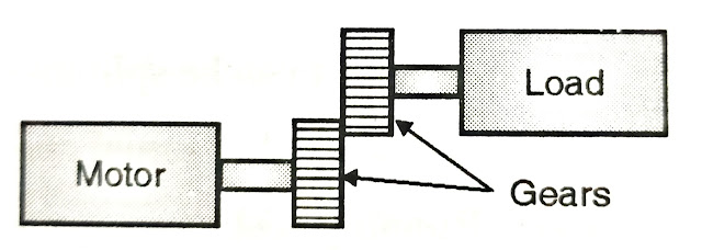
Gear Drive
Gear Drive

☞Modern straight cut gears and particular variation found in worm reduction drive are common features in many machines such as cloth calendar.


Single Phasing Preventer

Single Phasing Preventer:

✪The concept of single phasing is already explained in section 6.2.

✪When one of the phase is blown off due to open circuit or due to operation of fuse of that phase then three phase Induction motor still works with two phases.

✪The whole power is shared by remaining two phases, Thus, the current in these two

healthy phases increases b y √3 times. 

Causes of Single Phasing

✪increase in heating in motor windings.

✪unbalanced rotor currents produces negative phase sequence components. This component produces magnetic flux which rotates in opposite direction to main flux. There by double frequency currents are

induced in rotor causes rotor heating. 

✪This heating is not detected by replica type thermal relays used for protection of stater winding.

✪Also the phase over current relays act slowly. Hence single phasing causes major damage to rotor.

✪Single phasing preventers are generally used for small capacity motors. 

✪Fig.shows the connection scheme for single phasing preventer. 

✪Single phasing preventers are connected in secondaries of line CT.

✪These mainly contains a negative sequence filter.

✪The output of negative sequence filter is fed to a level detector. Further which sends tripping command to the starter or circuit breaker.

✪Thus it protects the motor from damage.

Single phase preventer